How to add overload circuit to my circuit Block diagram for inverter current control with voltage feed-forward Inverter circuit output load homemade corrected diagram circuits voltage parts list discussed independent correction automatic
Block diagram for inverter current control with voltage feed-forward
Inverter overload sinewave Block diagram of the inverter output voltage control. Short circuit protection circuit diagram
Inverter voltage
Inverter schematic inverters circuit pwm simplified passiveOverload inverter diagram protector circuit circuits delayed rest auto Overload circuits homemade inverters relayVoltage low circuit cutoff inverter diagram battery inverters power sponsored links.
Load independent/output corrected inverter circuit discussedLow battery and overload protection circuit for inverters Asoka technologies: a seven-level inverter with self-balancing and lowCircuit inverter low simple power diagram.

Super circuit diagram: simple low-power inverter circuit diagram
Input transistor simplifiedSchematic diagram of the inverter. 16 inverter overload circuit diagramCircuit inverter diagram expand click.
Low power inverter circuit diagramTronix technology: electrical projects Circuit overload diagramsOverload mosfet.
Inverter feedback circuit power diagram regulation low voltage sg3524 simple sponsored links
Schematic diagram of a three-level inverter connected to loadInverter seven level asoka technologies proposed circuit fig Inverter voltage feedTwo dies in one package: teardown of a vintage rom with double the storage.
Block diagram for inverter current control with voltage feed-forwardInverter overload protector Low power inverter circuit diagramInverter circuit 100w diagram schematic watt cd using circuits projects build transistor finder electronics power wave ac electrical project gr.

Inverter circuit diagram
Inverter schematic regulated converter ozone .
.


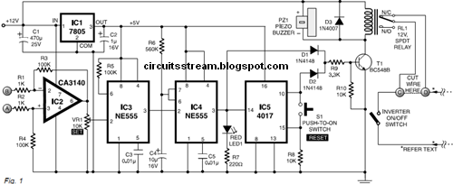
Low Battery and Overload Protection Circuit for Inverters - Homemade

Block diagram of the inverter output voltage control. | Download

16 INVERTER OVERLOAD CIRCUIT DIAGRAM - InverterDiagram
TRONIX TECHNOLOGY: ELECTRICAL PROJECTS

Load Independent/Output Corrected Inverter Circuit Discussed | Circuit

Schematic diagram of the inverter. | Download Scientific Diagram

Two dies in one package: Teardown of a vintage ROM with double the storage

Block diagram for inverter current control with voltage feed-forward